
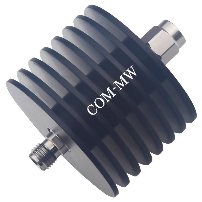
Attenuator
FrequencyDC~18GHz, Attenuation3dB, 20W, 50Ω, SMA-JK
- DA9-320-0-18000-832
- China
- One Year
- +86-19938031308
- sales@com-mw.com, cynthia@com-mw.com
- 3-1-2306, No.37 Jiancai Road, Chenghua Zone, Chengdu
- For qty details, please search in spot products of dianzibuy. Any changes to the contents are not notified. Please confirm again before ordering.
- No restrictions on export to any country
- RoHS compliant (Meet RoHS standards can be customized)
Product Details
Main specifications
| Parameters | Min | Typical | Max | Units |
| Frequency | DC | ~ | 18 | GHz |
| Attenuation | 2.4 | 3 | 3.6 | dB |
| VSWR | 1.35 |
Other parameters
| Power Capacity | 20W Design assurance |
| Impedance | 50Ω |
| Connector | SMA-JK |
| Connector material | Stainless steel |
| Surface | Black |
| Product shell material | Aluminum |
| Operation Temp. | -45~+85℃ Design assurance |
| Other | In put SMA-J |
Note
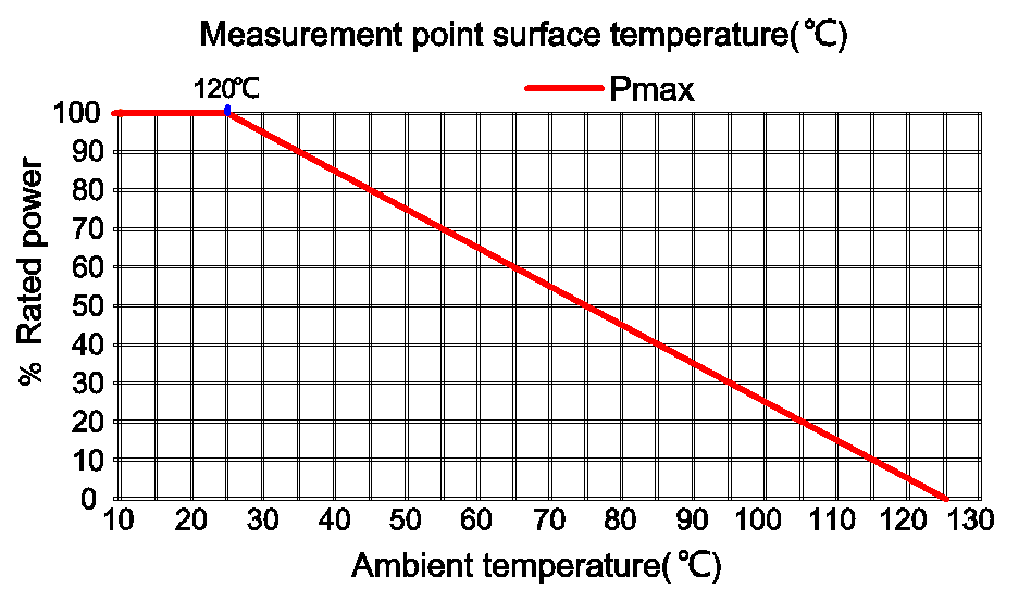
1. When installing attenuators, it is necessary to consider sufficient heat dissipation space and avoid installing them next to equipment with high heat output, otherwise the power capacity will decrease;
2. Small power attenuators do not have input and output directions, nor do they indicate directions. When high-power attenuators have input and output port markings, they must be connected to the equipment in the specified direction, otherwise the attenuator may burn out.
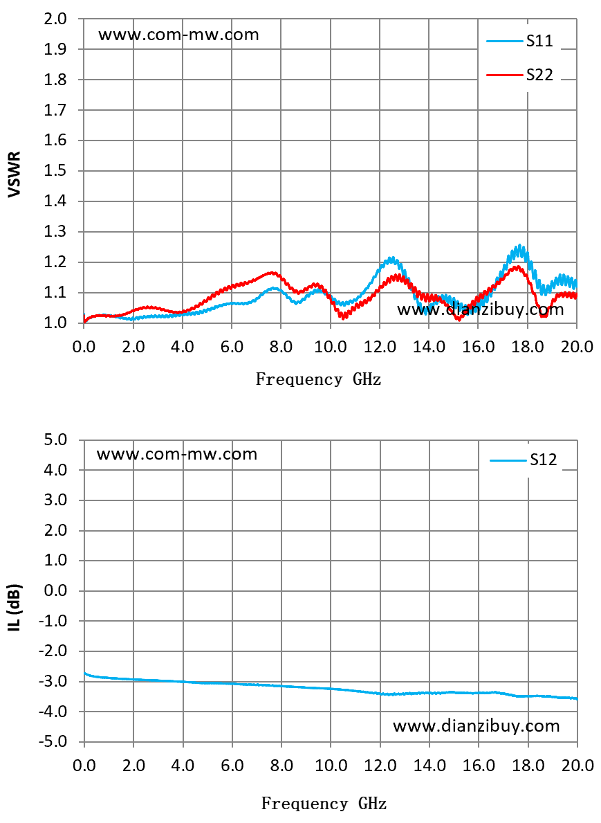
Typical test data
| Frequency GHz | S11 VSWR | S22 VSWR | S12 IL (dB) |
| 1.43 | 1.02 | 1.03 | -2.91 |
| 2.86 | 1.02 | 1.05 | -2.96 |
| 4.29 | 1.03 | 1.04 | -3.03 |
| 5.71 | 1.06 | 1.12 | -3.07 |
| 7.14 | 1.09 | 1.15 | -3.11 |
| 8.57 | 1.07 | 1.1 | -3.18 |
| 10 | 1.09 | 1.08 | -3.24 |
| 11.43 | 1.11 | 1.07 | -3.36 |
| 12.86 | 1.19 | 1.14 | -3.41 |
| 14.29 | 1.07 | 1.09 | -3.39 |
| 15.71 | 1.04 | 1.05 | -3.39 |
| 17.14 | 1.18 | 1.16 | -3.42 |
| 18.57 | 1.09 | 1.02 | -3.48 |
| 20 | 1.12 | 1.1 | -3.59 |
Power Derating Curve
Reference picture
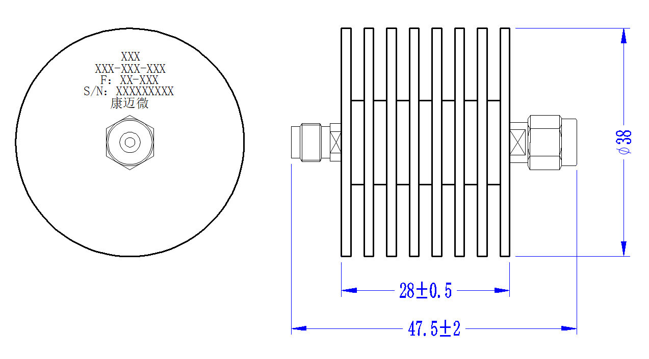
Configuration(mm)
Typical test curve